Knee Actuator System Interface Overview 
All of the work involved in running experiments with this knee stimulus system can be done from a workstation. The current configuration makes it very easy for the end-user to run experiments. The electro-hydraulic actuator is controlled digitally by a network of two INMOS T805 transputers.
Transputers are high performance microprocessors that support parallel processing. Some of the hardware features that are key to the support of parallel processing are the following: the transputers have a built in scheduler for processes running in 'parallel' on the same transputer, processes waiting for an event (input,output or timed event) consume no CPU resources, and communication links between transputers can occur on multiple links without the intervention of any of the processors. The transputers are programmable, in ANSI C, a feature that allows the controller to be as complex as the software that runs it. Another advantage is that it is possible to drastically change the controller's behaviour at any time with very little effort, a feature that is essential for the type of system which needs to be controlled ( refer to Performance Section of this document ). From the software programming end, the way the multi-process code for the INMOS transputers is written is very similar to the way it would be done in C, under UNIX.
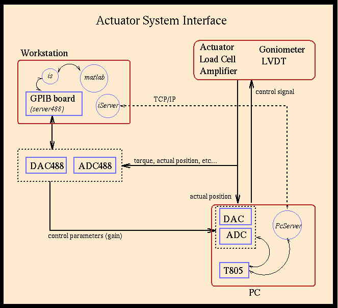
The transputers are mounted on an 80486 board and can be programmed through an 80486 processor. Under the current configuration, the end-user does not have to worry about these details since all of the interaction with the control system can be done through the workstation. As well, all of the inputs and outputs needed to run experiments can be set and obtained through a Graphical User Interface (GUI) running under Matlab. Although it is not necessary for the user to have a thorough understanding of the complete setup, it is good for him/her to have an idea of the interaction between the different components. The schematic below gives a high level overview of the setup.

The general running sequence of the controller is as follows. At startup, the controller is loaded on the transputer chips and they start executing it. Since the controller is continually processing inputs, it actually runs in an infinite loop. One of the transputers handles all of the communication with the PC and is only be active when the controller is being started. The other transputer gets the input signals, does all of the processing and feeds out the control signal. Note that the controller does its own conversion of input signals to digital and output signals back to analog. Some of the next pages in this document, Controller Setup Overview, and Controller Structure and Configuration, give more information on the way the transputers are configured.
The server488 program handles the control of the
DAC/ADC488 as well as certain filters, all used to manipulate the signals to
and from the matlab GUI. The matlab GUI can send digitally represented signals
to server488; these are then converted to analog before being sent to the
actuator control. In addition, server488 provides the output signal from the
actuator control, the actual position of the actuator ,the original input
signal, and the EMG outputs in digital form to the matlab GUI. The way
server488 controls the converters and filters is through a General Purpose Interface
Bus (GPIB) which is installed on the workstation. This hardware provides an
interface to link the workstation to the aforementioned electronic devices. The
GPIB actually uses an industry standard protocol (IEEE-488) to communicate with
the devices. The server488 is nothing but a software controller, or
interface, to the GPIB board. The matlab GUI has to use some 'client' code to
talk to the "server488". It uses the is client program to pass
and to receive any messages to the server. The figure above should give a clear
picture of the path of the different signals in the system