Current Performance 
The required performance of the knee controller is based on the study of other
joints. Since the elbow exhibits a reflex following a delay of 50ms, one would
expect the knee to have a similar reflex response. In fact, the reflex response
of the knee will probably be slower since the knee has higher inertia than the
elbow. As a result, a safe requirement to make sure that it is possible to
measure the response of the knee to an input signal, and be able to distinguish
the reflex response from the actual torque necessary to move the joint, is to
require that the actuator perform a 1mm step rise under 50ms. In other words,
the Bandwidth of the controller must be at least 20Hz.
![]()
Response to a Random Input Signal: taken on Nov 26, 1995
The following measurement was taken on Nov 26, 1995. It shows the response of the system to a random noise input.
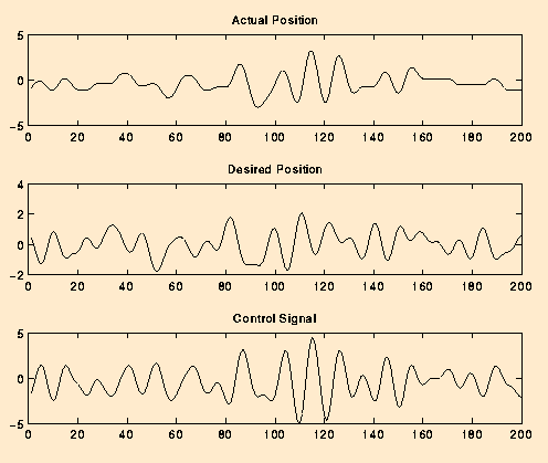
We can make the following comments about the system's response to random noise. The control system appears to be able to keep up with the input signal when it has a fairly high amplitude. Note that between the times of 80 and 120 ms, the desired and actual position are very close. During this interval, the desired position also happens to vary between +/- 3V, the largest amplitude difference of the whole sample. Outside of this range, the actual position does not track the desired position as well. The worst area is between 160 and 180 ms. During this phase, the actual position is almost constant while the desired position varies between approximately +/- 0.5 V. Note that even though the actual position stays near constant at times, the control system signal is never constant for any prolonged time interval.
The problem with the low amplitude input signals is that they bring the
actuator in its most nonlinear zone. When control inputs fall below the
threshold required to keep the actuator moving, the actuator enters its static
zone of operation. With the actuator stopped, the input necessary to make it
move again needs to be much larger than the previous threshold value because of
the big difference between the static and dynamic friction coefficients for the
hydraulic actuator. ![]()
Response to a Pulse Input Signal: taken on Nov 26, 1995
The following measurement was taken on Nov 26, 1995. It shows the response of the system to a pulse input.
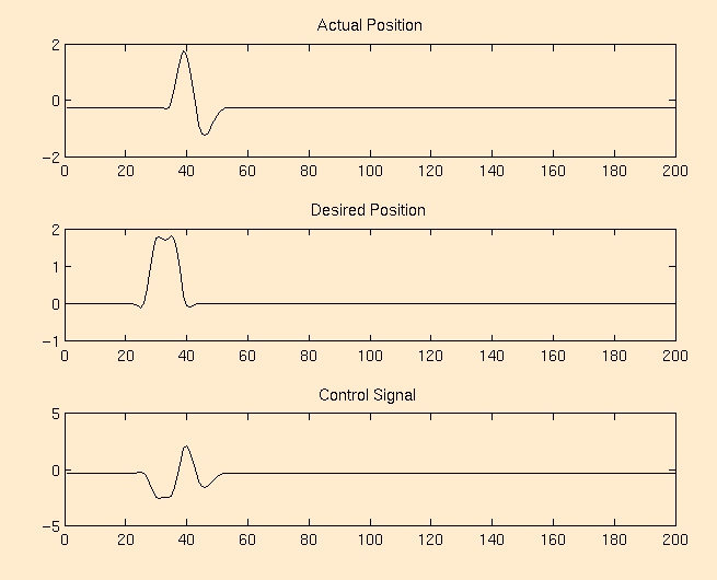
We can make the following observations about the system's response to the pulse input. The rising transition is very close to ideal: the actual position moves up to a voltage which is nearly identical to that of the desired position. Its step response is well under the rise time requirement outlined at the top of this section (step response reached 90% of the desired response in approximately 15ms : note that the displacement of the actuator for the 2 V input was greater than the 1 mm displacement requirement). On the falling edge of the input pulse, the response is much further from ideal. We overshoot by almost 1 V on the falling edge. Again, as with the random noise, our problems seem to be caused by friction, but also by inertia. The actual position is always lagging behind the desired position. When the actual position is approximately 2 V (the upper peak), the desired position is at 0V. Because of the difference in the errors of the samples taken over a short interval, it is not surprising to see the overshoot that we get. The derivative and proportional gains would both be really big, around time 40ms, something that we both want and need. The problem is that the control signal pulls on the actuator, too hard for too long. The inertia of the actuator, by the time it nears the 0V position is fairly large, and the actuator just keeps overshooting into the negative voltage range.
We look at some possible solutions to some of the aforementioned performance problems in the Suggestion section.
Note that the code used to run both of these experiments is called nonlin6.c, and its path can be found in the Reference Location page under nonlin6.c. This code implements a proportional and derivative gain control algorithm.
![]()
Last modified: Sat Dec 9 21:42:11 EST 1995