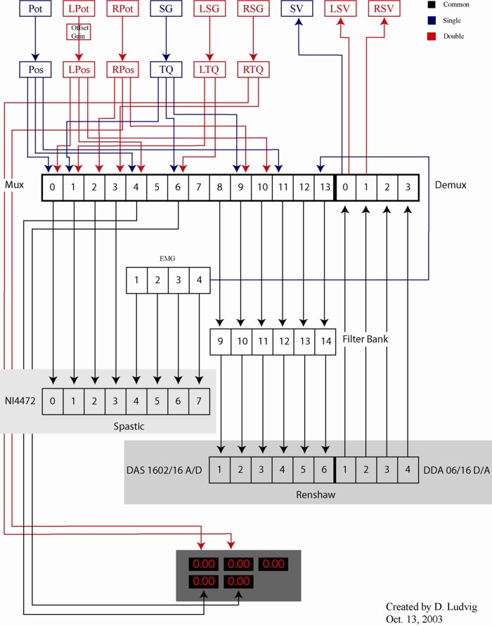
Combined Wiring for Supine and Standing Experimental Setups
|
MUX
|
|||||
|
Channel
|
Input A
|
Input B
|
Output
|
Measurand S
|
Measurand D
|
|
0
|
Pos
|
L Pos
|
Spastic 0
|
Position
|
Left Position
|
|
1
|
Tq
|
L Tq
|
Spastic 1
|
Torque
|
Left Torque
|
|
2
|
-
|
R Pos
|
Spastic 2
|
-
|
Right Position
|
|
3
|
-
|
R Tq
|
Spastic 3
|
-
|
Right Torque
|
|
4
|
Pos
|
L Pos
|
DD LL
|
Position
|
Left Position
|
|
5
|
-
|
-
|
-
|
-
|
-
|
|
6
|
Tq
|
L Tq
|
DD LM
|
Torque
|
Left Torque
|
|
7
|
-
|
-
|
-
|
-
|
-
|
|
8
|
-
|
-
|
Filter 9
|
-
|
-
|
|
9
|
Tq
|
R Pos
|
Filter 10
|
Torque
|
Right Position
|
|
10
|
-
|
L Pos
|
Filter 11
|
-
|
Left Position
|
|
11
|
Pos
|
-
|
Filter 12
|
Position
|
-
|
|
12
|
-
|
-
|
Filter 13
|
-
|
-
|
|
13
|
EMG 4
|
-
|
Filter 14
|
TA EMG
|
-
|
|
DeMUX
|
|||||
|
Channel
|
Input
|
Ouput A
|
Output B
|
Measurand S
|
Measurand D
|
|
0
|
Renshaw D/A 1
|
SV
|
LSV
|
Command
|
Left Command
|
|
1
|
Renshaw D/A 2
|
-
|
RSV
|
-
|
Right Command
|
|
2
|
Renshaw D/A 3
|
-
|
-
|
-
|
-
|
|
3
|
Renshaw D/A 4
|
-
|
-
|
-
|
-
|
|
Spastic
|
|||
|
Channel
|
Input
|
Measurand S
|
Measurand D
|
|
0
|
Mux 0
|
Position
|
Left Position
|
|
1
|
Mux 1
|
Torque
|
Right Position
|
|
2
|
Mux 2
|
-
|
Left Torque
|
|
3
|
Mux 3
|
-
|
Right Torque
|
|
4
|
EMG 1
|
-
|
-
|
|
5
|
EMG 2
|
-
|
-
|
|
6
|
EMG 3
|
-
|
-
|
|
7
|
EMG 4
|
TA EMG
|
-
|
|
Renshaw A/D
|
|||
|
Channel
|
Input
|
Measurand S
|
Measurand D
|
|
1
|
Filter 9
|
-
|
Right Position
|
|
2
|
Filter 10
|
Torque
|
Left Position
|
|
3
|
Filter 11
|
-
|
-
|
|
4
|
Filter 12
|
Position
|
-
|
|
5
|
Filter 13
|
-
|
-
|
|
6
|
Filter 14
|
TA EMG
|
-
|
|
Renshaw D/A
|
|||
|
Channel
|
Output
|
Measurand S
|
Measurand D
|
|
1
|
Demux 1
|
Command
|
Left Command
|
|
2
|
Demux 2
|
-
|
Right Command
|
|
3
|
Demux 3
|
-
|
-
|
|
4
|
Demux 4
|
-
|
-
|
original wiring diagram available in Adobe Illustrator: wiring diagram.ai
original wiring tables available in Excel: wiring tables.xls