Ultrasonic Sensor
UNDK 20U6914/S35A
Ultrasonic Sensor with Analogue Output
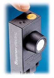
A special sonic transducer is used for the ultrasonic proximity sensors, which allows for alternate transmission and reception of sound waves. The transducer emits a number of sonic waves which are reflected by an object, back to the transducer. After emission of the sound waves, the ultrasonic sensor will switch over to receive mode. The time elapsed between emitting and receiving is proportional to the distance of the object from the sensor. Ultrasonic proximity sensors enable the detection of different objects irrespective of color and transparency.
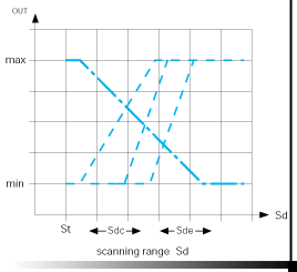
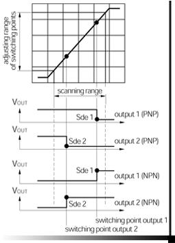
Both current and voltage outputs of the proximity sensors, are proportional
to the distance to the target. The user can change the slope of the output curve
using the built-in potentiometer or teach mode button. By doing so they are
able to define the required resolution. Sensor versions, which have a built-in
A/D-Converter, generate output signals divided into discrete steps. Applications
having long cable runs where there might be EMI or RFI interferences should
use sensors with an analog current output.
The analog output can be set to either rise or fall proportional to the target distance.

The data sheet for the UNDK sensor:
Operating Instructions
Teach-in locking 5 min. after every power-up, respectively after the end of the last Teach-in process.
Adjustment of 0…10V operation range
1. Adjustment mode: Press the Teach-in button or connect the white Teach-in
wire +Vs for approximately 2 seconds until the bicolour LED flashes amber/red.
Release button or disconnect Teach-in wire.
2. LED flashes red. Place the target at the required sensor close limit (i.e.
the closest the target will get to the sensor - Sdc=0V) and press the Teach-in
button or connect the external white Teach-in wire to +Vs.
3. LED flashes amber. Place the target at the required sensor far limit (i.e.
the farthest the target will be from the sensor - Sde=10V) and press the Teach-in
button or connect the external white Teach-in wire to +Vs.
4. Successful completion of Teach-in procedure is confirmed by both LEDs being
"on" for approximately 2 seconds.
Adjustment of 10V…0V operating range
1. Adjustment mode: see paragraph 1 above.
2. Place the object first at the sensor far limit (Sde=0V) and proceed according
to paragraph 2 above.
3. Place the object at the sensor close limit (Sdc=10V) and proceed according
to paragraph 3 above.
4. Successful completion of Teach-in procedure.
Resetting to original factory settings
Performing steps 1 and 2 above without an object within the sensor's range,
or holding the button down for more than 6 seconds, will automatically restore
the original factory settings. Fast flashing of both LEDs indicates successful
completion of the resetting.


Last modified: 2003-08-07 Shauna Forster