Servo-valve
module
II
Schematic
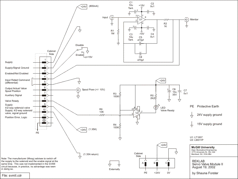
- LT1007 operational amplifier
- LM311P operational amplifier
- Capacitors
- Resistors
- switches (C&K 7101)
- green LEDs (Lumex part #SSI-LX312GD-150)
- BNC connectors
- Hirschmann 11+PE surface mounted connectors (Hirschmann 932 628-206)
- 3-pin Amphenol female receptacle
connectors (Amphenol part #16S-5S)
Functional description
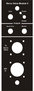
faceplate available in CorelDraw10 file: svmII faceplate.cdr
The role
of the SVMII module is to send a 24 volt DC supply and the command signal
to the servo-valve. The 24V supply originates from the SVMII power supply
panel and is inputted to the SVMII module through the 3-pin Amphenol connector.
The 24 VDC supply and ground is sent to pin 1 and 2, respectively, of the
servo-valve, and also to the fail-safe solenoid valve, pin 10 and 11, respectively.
The command signal
from the controller is inputted to the module via the input BNC. The LT1007
operational amplifier is used to drive the long cables connecting the module
to the servo-valve. The monitor BNC shows the output of the op amp. The enable/disable
switch sends a signal to pin 3 of the servo-valve. If the 24VDC is being supplied
to the valve and the enable switch is on, the LED will light up.
Last modified: 2003-07-24 Shauna Forster