Servo-valve
module
Schematic
The
components used in this module are:
- LH0021CK operational amplifier
- Capacitors
- Resistors
- Cannon connector
- BNC connector
Functional description
faceplate.cdr: CorelDRAW 9.0 file used to make faceplates
This
module is a voltage-to-current converter that is used to drive the servo-valve.
The input voltage to this module comes from the transputer and is controlled
by the desired output position of the actuator (remembering that 0.1 rad=1
volt) and the servo gain. All these parameters are set in the ankle_gui in
Matlab.
This
input voltage is then converted to current in the servo-valve module based
on the transfer function of the circuit, which is Iout/Vin=2mA/V. To
determine how much current will drive the servo-valve, take this simple example.
We want to displace the actuator by 0.1 rads and set the servo gain to 1.
Therefore 1 volt is input to the module and 2mAmps will drive the servo-valve
to move the actuator 0.1 rads.
The
servo valve is connected across pins A and B of the cannon receptacle. The
current that drives the servo-valve also flows through the 10 ohm resistor
connected to ground. The voltage across this resistor is output via the V
to I BNC and is V=Iservo*R=Iservo*10. Therefore, Iservo=V/10
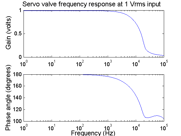
Frequency
response
The
frequency response at a Vrms of 1 and 10 produce a gain at 1 with a roll off at
1KHz. The phase is 180 during the pass region and rolls off in the transition
region.
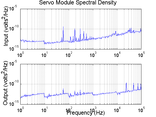
Noise
analysis
The noise analysis to a 0 volt input shows that the module produces very little noise.
Last modified: November 14, 2001 Laura Galiana