Rectifier Module
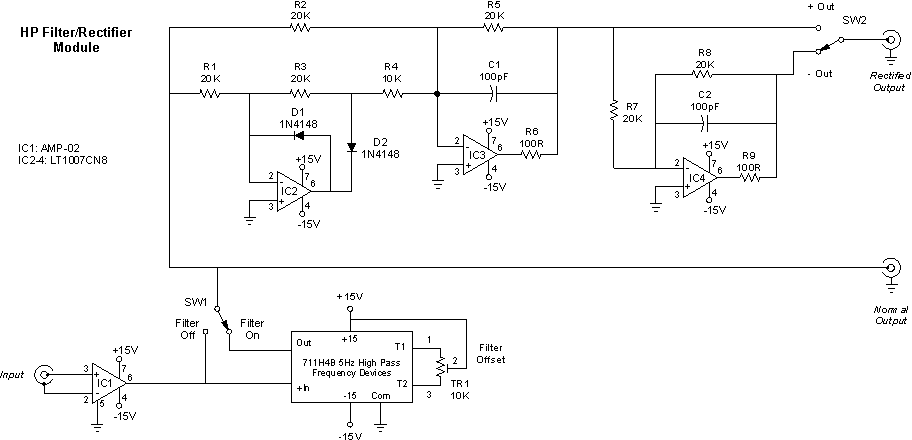
Schematic
The rectifier portion of this module is composed of:
· 1% metal film ¼ watt resistors
· LT 1007 operational amplifiers
· IN916C Diodes

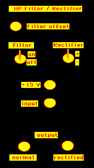
Front panel
Input:
The input signal from the EMG amplifier is applied to the input BNC connector on the front panel.
Outputs:
If the signal is to be high-pass filtered only, the output BNC should be connected to the Normal output BNC and the filter switch placed to ON.
If the input is to be rectified only, the ouput has to be connected to the rectified BNC output and the filter switch must be set to OFF.
The rectifier switch can be set to positive or negative rectification. In our lab, the Tibialis Anterior EMG is positively rectified, whereas the Gastrocnemius EMG is negatively rectified.
If the output is to be rectified and filtered, the output has to connected to the rectified BNC with the filter switch ON. You may also have an output of 15V at the 15V output BNC.
|
Case |
Filter switch
|
Output BNC
|
Rectifier switch
|
|
HP filtered only
|
ON
|
Normal
|
Doesn't matter
|
|
Rectified (+/-) only
|
OFF
|
Rectified
|
+ or -
|
|
HP filtered and rectified
|
ON
|
Rectified
|
+ or -
|
|
15 volts
|
Doesn't matter
|
15 V
|
Doesn't matter
|
Filter
The high pass filter is a fourth order ( 80 dB roll-off/decade) Butterworth filter from Frequency Devices (711H4B) with a corner frequency at 5Hz. The gain in the pass band region is 0 dB. The phase is 0 degrees in the stop-band region, -90 degrees at the corner frequency and -180 degrees in the pass-band region. (See fig hpfilt for Bode plot). The noise analysis of the filter was very low. (See fig filtnoise)Rectifier
The EMG signal is input to the circuit via a BNC connector on the front panel of the module. The rectified or normal signals can obtained from the two parallel output channels. The can be filtered and rectified or a combination of the two via the filter and rectifier switches on the front panel.
List of Components
· 3 LT1007 Operational Amplifier
· Dielectric Capacitors
· +/- 10% Resistors
· 2 1N916C Signal Diodes
Functional Specifications
This module requires +/- 15 Volt power supply to operate.
Please send any questions regarding the information here to:
