Potentiometer Module
Functional Description
Brief Description: This module takes the signal from the potentiometer, amplifies it and puts an offset on the signal. The gain and offset of the potentiometer to be changed from the front panel controls.
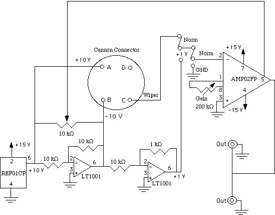
The schematic of a typical Potentiometer Module is presented below. To enlarge the schematic, click on it.
This schematic gives an example of a circuit for a Potentiometer Module. This circuit changes the gain and the offset of the potentiometer.
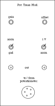
Front Panel
Inputs:
There one input to this module. The wiper from the potentiometer is the input to the instumentation amplifier. +/- 10 Volts is applied across the potentiometer. The instrumentation amplifier measures the voltage from the wiper to ground (the center of the potentiometer).
Outputs:
Two parallel outputs channels and a single output channel are provided on the output. The single output channel is described above as the wiper output of the potentiometer. The single output is used to drive the servo-motor. The parallel output channels provide a variable gain in volts. The gain for the module can be adjusted from the gain and offset adjust knob on the front panel of the module.
Trim Gain Switch
Varies the gain multiplier from 1000 to 0.001. The step size of the gain is determined by the user.
Offset
The offset adjust switch sets the amount of offset on the output signal. The amount of offset on the output signal is determined by the user.
Gain Selection
The gain of the output amplifier is determined by the trim gain.
Circuit Diagram
Potentiometer Module Schematic
The figure above shows the schematic of the Potentiometer Module used in this lab.
Operation
The output of the two parallel outputs is the gain times the wiper voltage plus the offset.
Gain Setting
To set the gain of the amplifier, adjust the gain-trim to get the desired output values.
List of Components
· 2 LT1001 Operational Amplifier
· 1 AMP02FP Operational Amplifier
· +/- 10% Resistors
· 2 Potentiometers
· 1 Cannon Connector
· 1 REF01CP Voltage Reference
Functional Specifications
This module requires +/- 15 Volt power supply to operate.
The Phase characteristics of this module are:
180 degree phase shift from 316 mHz to 90 kHz; after 90 kHz there is a 225 degree phase shift.
The Gain characteristics of this module are:
10 dB gain from 316 mHz to 90 kHz; after 90 kHz there is a 2-3 dB/decade rolloff.
The Noise characteristics of this module are:
There is a -80 dB SNR 0.1 Hz to 10 kHz; after 10 kHz the SNR increases slightly to about -75 dB.
Please send any questions regarding the information here to:

