Potentiometer
Module
Schematic
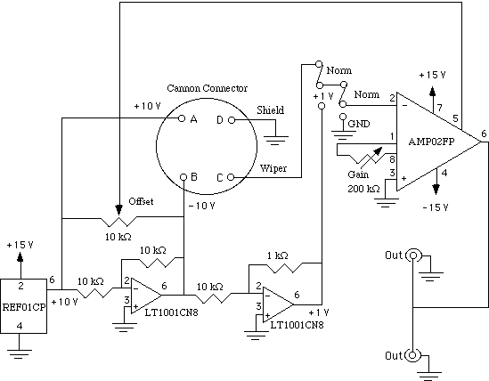
Components:
- LT1001
operational amplifiers
- REF01CP
reference voltage source
- Cannon connector
- AMP02FP
Instrumentation amplifier
- Variable resistors
- Resistors
- SP 3 position switches
- BNC connectors
Functional description
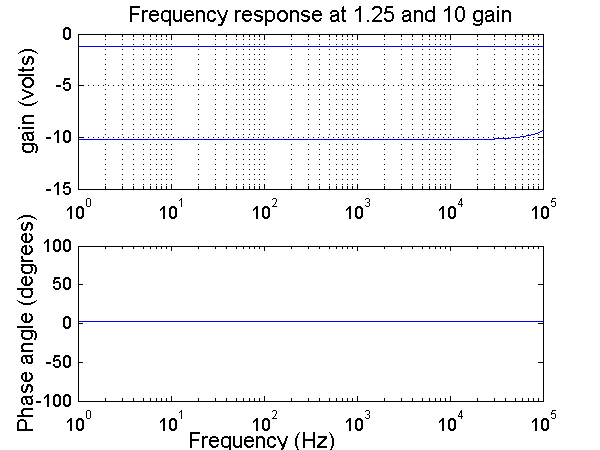
The purpose of this module is to condition the output of a potentiometer. The potentiometer measures the angular displacement of a wiper. This angular displacement is converted to a voltage between -10 and 10 volts (across pins A and C) in this module . The offset adjustment is used to set a known angle to a particular voltage. The gain adjustment is used to set the change in angle to a desired change in voltage. For example, a certain angle (say the ankle at neutral position) could be set to zero volts and an angular change of 90 degrees could be set to 9 volts. Therefore Vout=offset+gain*(deg/volt). In the ankle setup, the potentiometer module has been calibrated to produce a sensitivity of 10 V/rad.
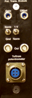
faceplate.cdr: CorelDRAW 9.0 file used to make faceplates
The
switch settings for switch 1 are NORM, NIL, and GND and for switch 2 they
are 1V, NIL, and GND. The NIL position is useless and the switches could be
replaced by SPDT switches. The gain and offset of the input are adjusted via
trim potentiometers. The minimum gain that can be set is 1.25 since the instrumentation
amplifier has a gain of (50k ohms/x)+1, where x is a variable resistor
of 200 K ohms.
To adjust the offset and gain: