Offset-Gain module
Schematic

Components:
- resistors
- LT1007 operational amplifiers
- LT1001 operational amplifier
- Variable resistors
- REF 01 reference voltage source
- BNC connectors
- SPDT switches
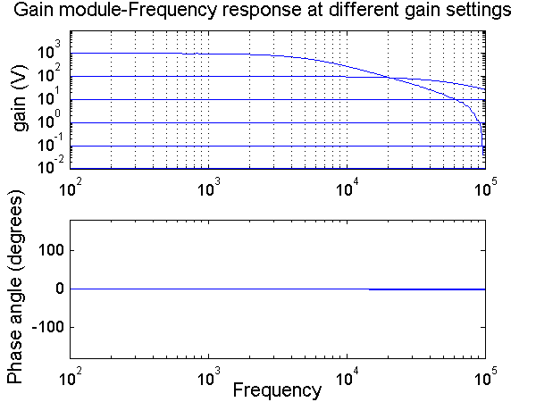
Functional description
This
module is used to adjust the gain of two inputs and ouptut their sum. The
same output can be viewed on each of the OUT BNCs.
·
NORM: input is connected to IN BNC
·
0 V: input is grounded and disconnected from input BNC
·
1 V: input is connected to a 1 Volt reference output.
The
rotary gain switch varies the gain multiplier from 0.01 to 1000
by using the following resistors:
|
Switch
position |
Gain |
Resistance
(ohms) |
|
-2 |
0.01 |
10 |
|
-1 |
0.1 |
100
|
|
0 |
1 |
1K
|
|
1 |
10 |
10
K |
|
2 |
100 |
100 |
|
3 |
1000 |
1
M |
The gain trim potentiometer adjusts
the gain by a scale factor ranging from +1 to –1.
In order to set
the gains, follow this procedure: