Preamplifier
Schematic

EMG signals are of very low amplitude and they need to be amplified to be
viewed. This module is a 3 stage pre-amplifier for EMG signals. The first
stage is an instrumentation amplifier (analog Devices AD625) with a gain of
10 (due to 4.42K ohms) or 100 (due to 402 ohms). The second stage is a bandpass
filter composed of resistors and capacitors with corner frequencies (defined
by 1/(2*pi*R*C)) of 1.06 Hz and 1591 Hz. The third stage is an isolation amplifier
(AD210) with a gain of 100 (100K/1K). The
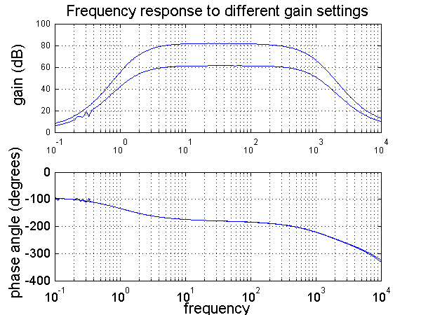
overall amplification is 1000 (60 dB) or 10 000 (80 dB) selected with a switch.
A
15 volt source is applied at the 15 V in connector. The 15V thru connector
is used to piggy back the voltage source to another EMG pre-amplifier. The
two leads to the electrodes are connected via the red terminal connectors
(R), whereas the reference electrode (electrode on a bony surface of subject)
is connected to the black terminal (B). The amplified EMG signal is output at the OUT
BNC connector.
The
frequency response is flat at the gain level between the two corner frequencies
of 1.06 Hz and 1591 Hz. The phase is –90 degrees in the stop-band region,
-180 degrees in the pass-band region, and –360 degrees in the second stop-band
region.