Ankle
Setup Potentiometer Module
Calibration
Objective
Obtain a potentiometer module signal sensitivity of 10 V/rad (or 0.1
rad/V) by setting the gain of the potentiometer module.
According to the potentiometer manufacturer's specs, the device provides
a nominal 346 degree travel range. Since this is not exact, it cannot
be used to accurately determine the potentiometer's natural sensitivity; a
calibration must be performed.
Method
1. Trim the potentiometer module gain to 2. (Any known low value will
do -- though a gain of 1 is not achievable on the pot module.)
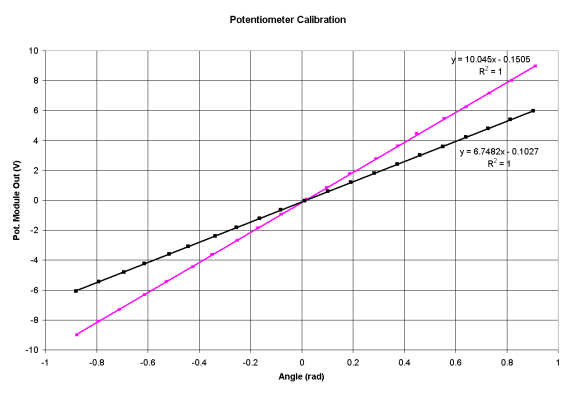
2. Determine the current static sensitivity of the pot/pot-module combination.
A 21-point curve of the actuator angle vs. module output was determined (black
markers and curve.) A precise Mitutoyo goniometer was used to measure the
angle. A X12 magnifying glass was used to read the ruled scale. The slope
of the resultant calibration curve indicates a potentiometer sensitivity
of 3.374 = 6.7482/2.
3. Adjust the pot-module gain to 2.964 = 10/3.374 to obtain the overall
desired pot/module sensitivity.
4. Re-do the calibration, as in step 2, to confirm the sensitivity setting
(magenta markers and curve.)

Note that the offset in the calibration curve is not that important. The servo
controller takes this offset into account at startup. Also, the offset will
change when the helical coupling is loosensed and tightened during maintenance.
History
2001-12-12: Calibration regression equation: y = 10.03x - 0.0705; R^2 = 0.9999
2004-06-08: Calibration regression equation: y = 10.045x - 0.1505; R^2 =
1
